11 Jun 2025
I’ve long had the dream of creating high resolution chains on characters with raymarching. The problem is that Unity’s object transform is based on the character’s hip bone, so making raymarched geometry “stick” to characters is impossible.
The idea I’ve been toying with for a long time is to raymarch inside a rasterized box. If you store information in that box’s verts, you could do a raymarch inside a wholly self contained coordinate system. I’ve pulled this off, but not in a way which is useful for characters (yet).
TLDR:
The core idea is to make it possible for each fragment of a material to learn an origin point’s location and orientation. If you can recover an origin point and a rotation, then you can raymarch inside that coordinate system, then translate back to object coordinates at the end.
For each submesh* in a mesh, I bake an origin point and an orientation.
* A submesh is just a set of vertices connected by edges. A mesh might contain many unconnected submeshes. For example, in blender, you can combine two objects with ctrl+J. I call those two combined but unconnected things submeshes.
The orientation of the submesh is derived from the face normals. I sort the faces in the submesh by their area. The largest area face is used as the first basis vector of our rotated coordinate system. Then I get the next face which is sufficiently orthogonal to the first basis vector (absolute value of dot product is > some epsilon). I orthogonalize those two basis vectors with graham-schmidt, then generate the third with a cross product. I ensure right-handedness by checking that the determinant is positive, then convert to a quaternion. I then store that quaternion in 2 UV channels.
The rotation quaternion is recovered on the GPU as follows:
float4 GetRotation(v2f i, float2 uv_channels) {
  float4 quat;
  quat.xy = get_uv_by_channel(i, uv_channels.x);
  quat.zw = get_uv_by_channel(i, uv_channels.y);
  return quat;
}
...
RayMarcherOutput MyRayMarcher(v2f i) {
...
  float2 uv_channels = float2(1, 2);
  float4 quat = GetRotation(i, uv_channels);
  float4 iquat = float4(-quat.xyz, quat.w);
}
It’s worth lingering here for a second. Each submesh is conceptualized as a rotated bounding box. We just deduced an orthonormal basis for that rotated coordinate system. That means that the artist can rotate their bounding boxes however they want in Blender, and the plugin will automatically work out how to orient things. You can arbitrarily move and rotate your bounding boxes and it Just Works.
The origin point is simply the average of all the vertex locations. I encode it as a vector from each vertex to that location, and stuff it into vertex colors. Since vertex colors can only encode numbers in the range [0, 1], I use the alpha channel to scale the length of each vertex.
I made two non obvious decisions in the way I bake the vertex offsets:
The offsets are encoded in terms of the rotated coordinate system. This saves one quaternion rotation in the shader.
The offsets are scaled according to the L-infinity norm (Manhattan distance) rather than the standard L2 norm (Euclidian distance). This lets the artist think in terms of the bounding box dimensions rather than the square root of the sum of squares of the box’s dimensions. Like if your box is 1x0.6x0.2, then you can just raymarch a primitive with those dimensions and your simulation Just Works.
The origin point is recovered on the GPU as follows:
float3 GetFragToOrigin(v2f i) {
  return (i.color * 2.0f - 1.0f) / i.color.a;
}
RayMarcherOutput MyRayMarcher(v2f i) {
...
  float3 frag_to_origin = GetFragToOrigin(i);
}
With those pieces in place, the raymarcher is pretty standard, but some care has to be taken when getting into and out of the coordinate system. Here’s a complete example in HLSL:
RayMarcherOutput MyRayMarcher(v2f i) {
  float3 obj_space_camera_pos = mul(unity_WorldToObject,
      float4(_WorldSpaceCameraPos, 1.0));
  float3 frag_to_origin = GetFragToOrigin(i);

  float2 uv_channels = float2(1, 2);
  float4 quat = GetRotation(i, uv_channels);
  float4 iquat = float4(-quat.xyz, quat.w);

  // ro is already expressed in terms of rotated basis vectors, so we
  // don't have to rotate it again.
  float3 ro = -frag_to_origin;
  float3 rd = normalize(i.objPos - obj_space_camera_pos);
  rd = rotate_vector(rd, iquat);

  float d;
  float d_acc = 0;
  const float epsilon = 1e-3f;
  const float max_d = 1;

  [loop]
  for (uint ii; ii < CUSTOM30_MAX_STEPS; ++ii) {
    float3 p = ro + rd * d_acc;
    d = map(p);
    d_acc += d;
    if (d < epsilon) break;
    if (d_acc > max_d) break;
  }
  clip(epsilon - d);

  float3 localHit = ro + rd * d_acc;
  float3 objHit = rotate_vector(localHit, quat);
  float3 objCenterOffset = rotate_vector(frag_to_origin, quat);

  RayMarcherOutput o;
  o.objPos = objHit + (i.objPos + objCenterOffset);
  float4 clipPos = UnityObjectToClipPos(o.objPos);
  o.depth = clipPos.z / clipPos.w;

  // Calculate normal in rotated space using standard raymarcher
  // gradient technique
  float3 sdfNormal = calc_normal(localHit);
  float3 objNormal = rotate_vector(sdfNormal, quat);
  o.normal = UnityObjectToWorldNormal(objNormal);

  return o;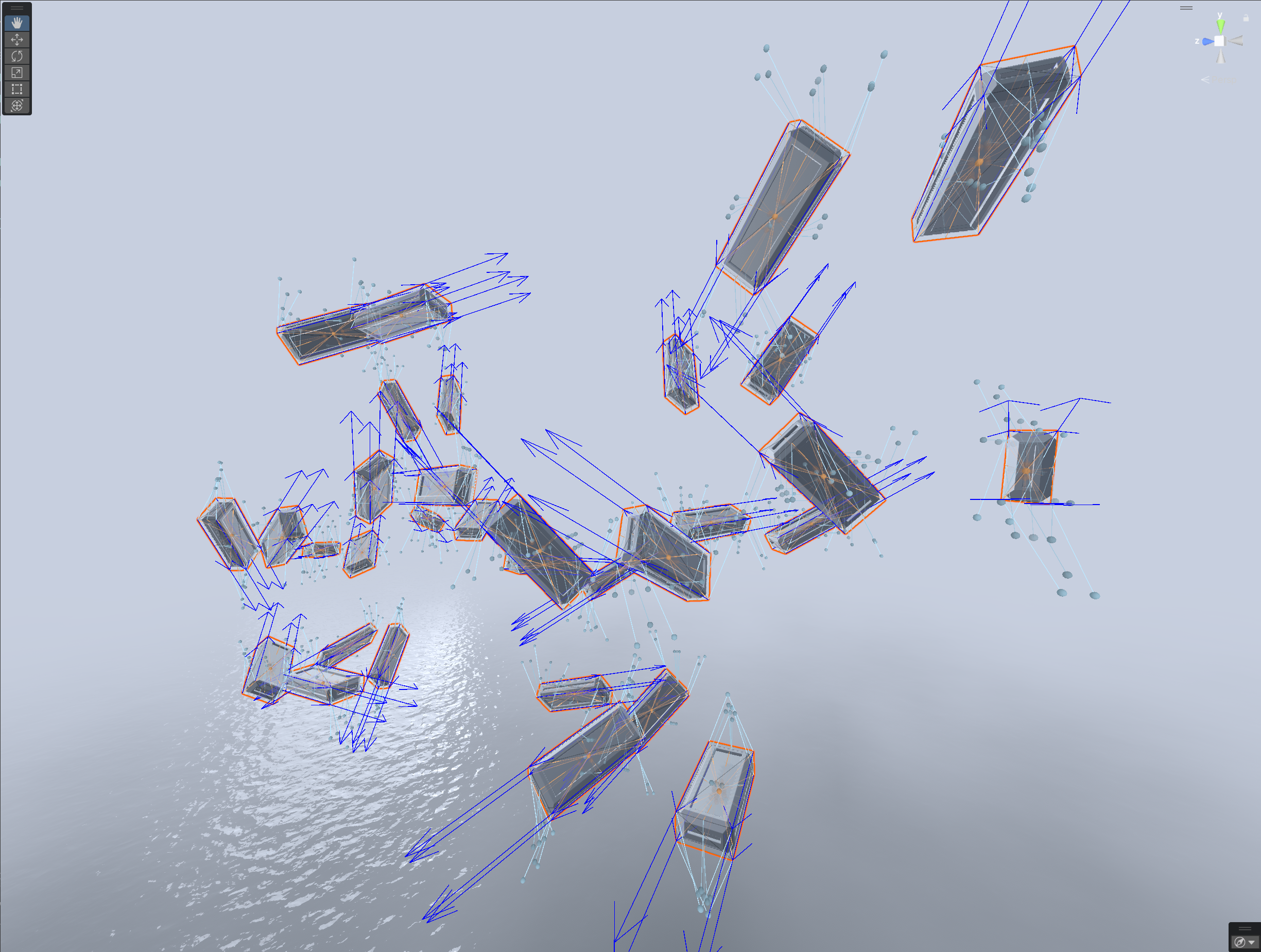
}This technique is extremely scalable. I have a world with 16,000 bounding boxes that runs at ~800 microseconds/frame without volumetrics.
You can have overlapping raymarched geometry without paying the usual 8x slowdown of domain repetition.
You still pay the price of overdraw, and unlike domain repetition, there’s no built-in compute budgeting. I.e. with domain repetition you’d hit your iteration cap and stop. With this you won’t.
The workflow is artist friendly. You can move, scale, and rotate your geometry freely. Re-bake once you’re done and everything just works.
Shearing works, but doesn’t permit re-baking.
I’ve written a Blender plugin to permit myself to bake the vectors and quaternions as described above.
The plugin supports baking vectors and quaternions on extremely large meshes primarily through caching. If your mesh contains many submeshes that are simply translated in space, then baking should take less than a second. If those submeshes are scaled, skewed, or rotated, then they won’t cache and baking will take longer.
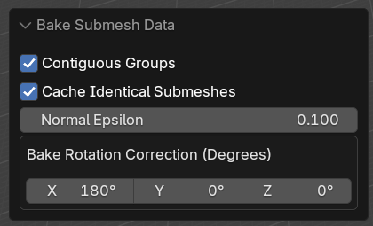
The baker lets you rotate the baked quaternion around the basis vectors. I had to fuck with this a fair bit, and eventually found that 180 degrees worked. Try going through every combo of 90 degrees (64 total) if you run into trouble. Use quick exporter to speed up the process. You can visualize the vectors with my Unity script, which is described below.
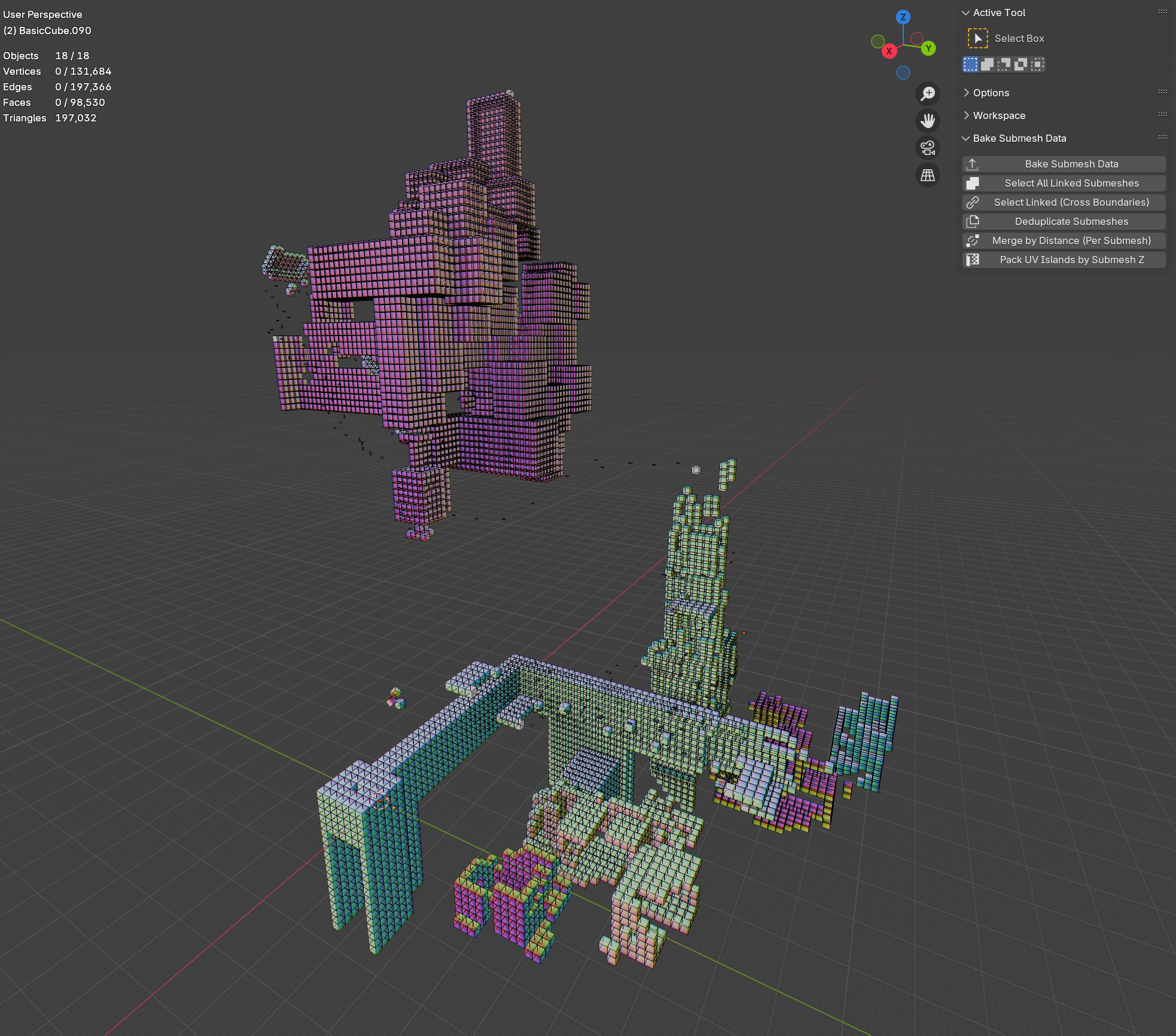
It also supports a bunch of other workflows, mostly designed for the voxel world creation workflow:
Select all linked submeshes. This just does ctrl+L for each submesh with at least one vert, edge, or face selected. Blender’s built in ctrl+L seems to be inconsistent in its behavior.
Select linked across boundaries. This basically does ctrl+L, but lets the meshes be disconnected at as long as they have a vert that’s within some epsilon of a selected vert. That epsilon is configurable. It’s scalable up to thousands of submeshes.
Deduplicate submeshes. This just looks for submeshes where all their verts are close to others. The closeness parameter (epsilon) is configurable. It works via spatial hashing so it’s extremely scalable.
Merge by distance per submesh. This just iterates over all submeshes and does a merge by distance on each. When working with large collections of submeshes, it’s easy to accidentally duplicate a face/edge/vert along the way, and these duplications can stack up. This lets you recover.
Pack UV island by submesh Z. This lets you pack UV islands for large collections of submeshes and sort them by their Blender z axis height. Buggy as shit rn, sorry!
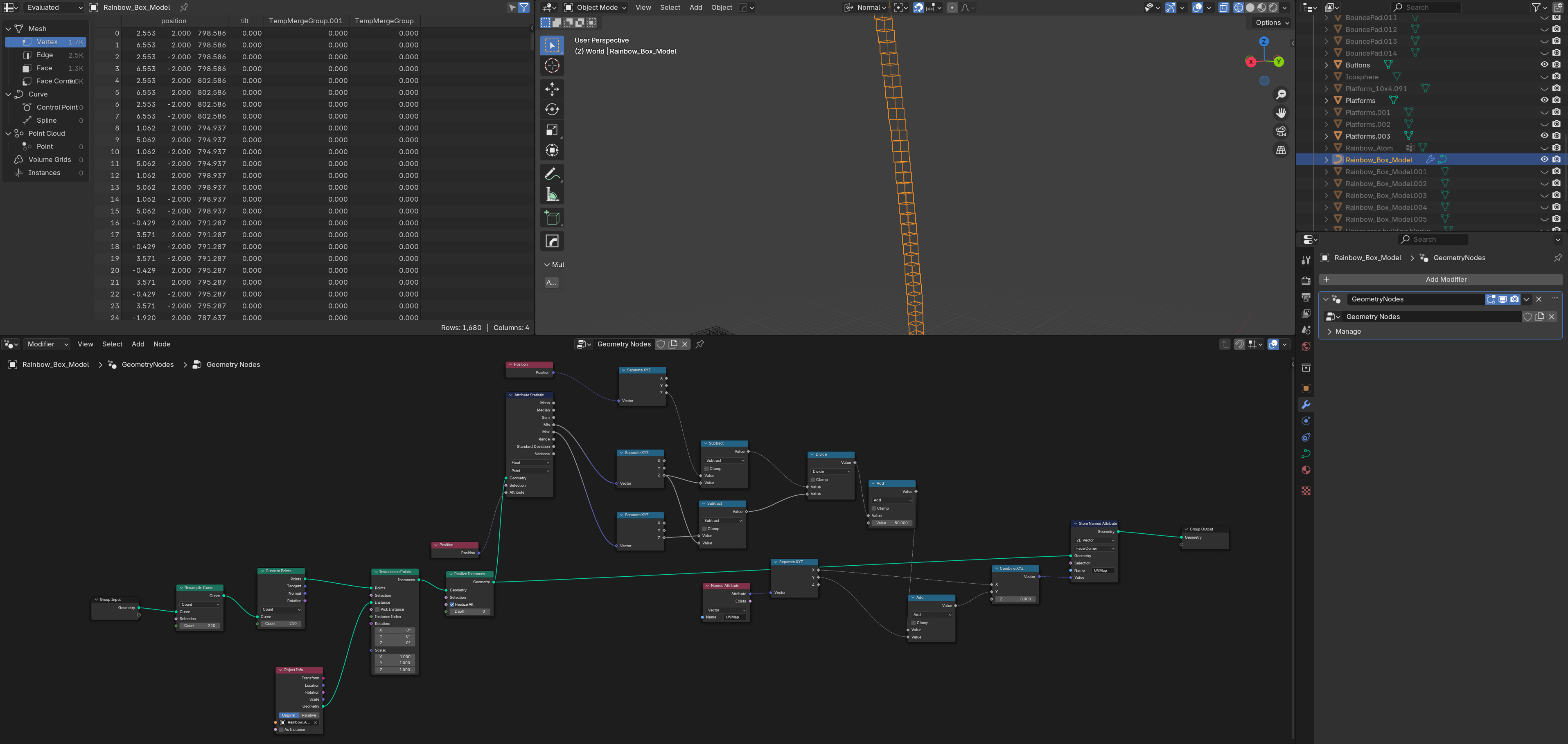
This is less relevant, but I wanted some way to instance axis-aligned geometry along a curve and sort each instance’s UVs by Z height. These nodes do that. Put them on a curve and select your instance. Then use the “Pack UV island by submesh Z” plugin tool to actually pack them.
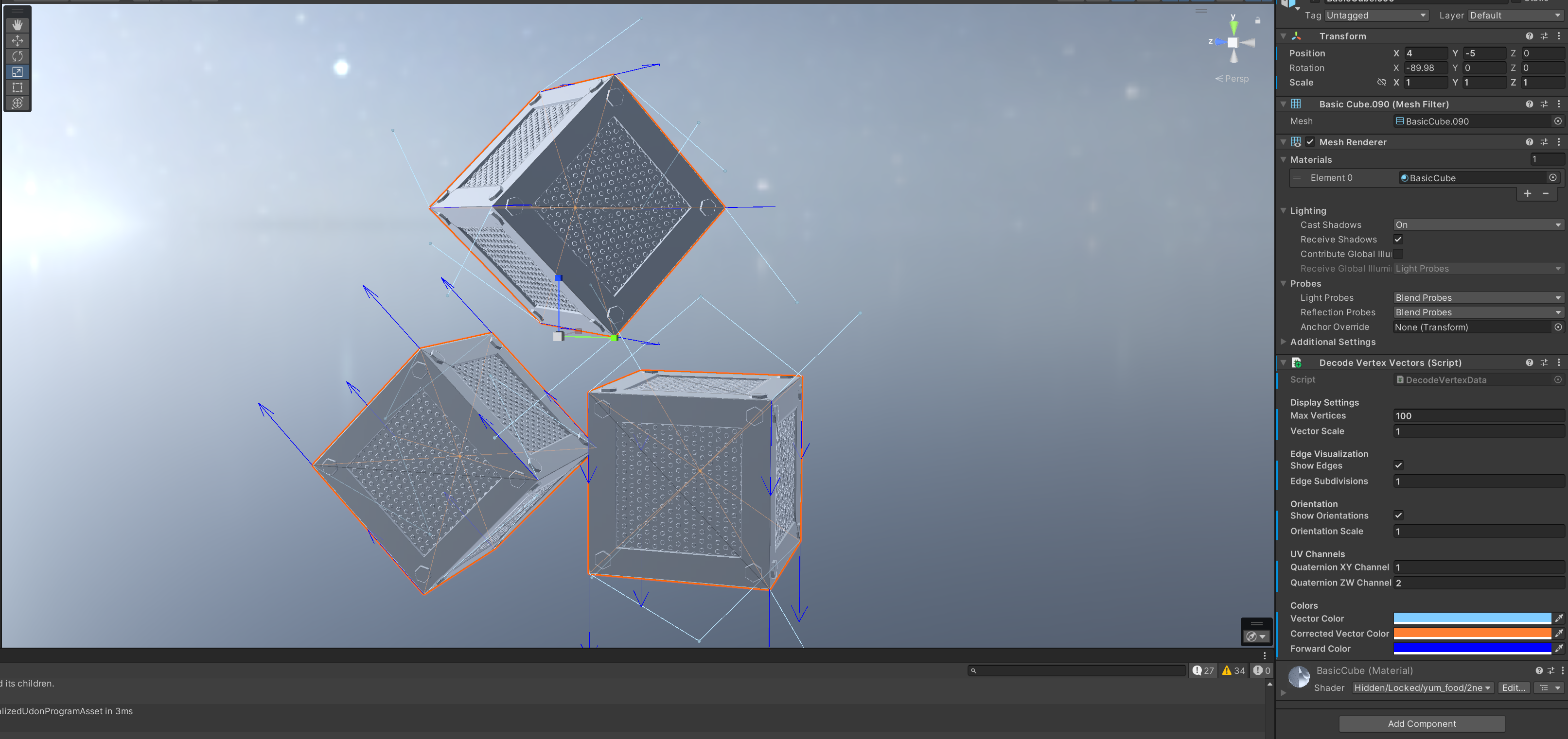
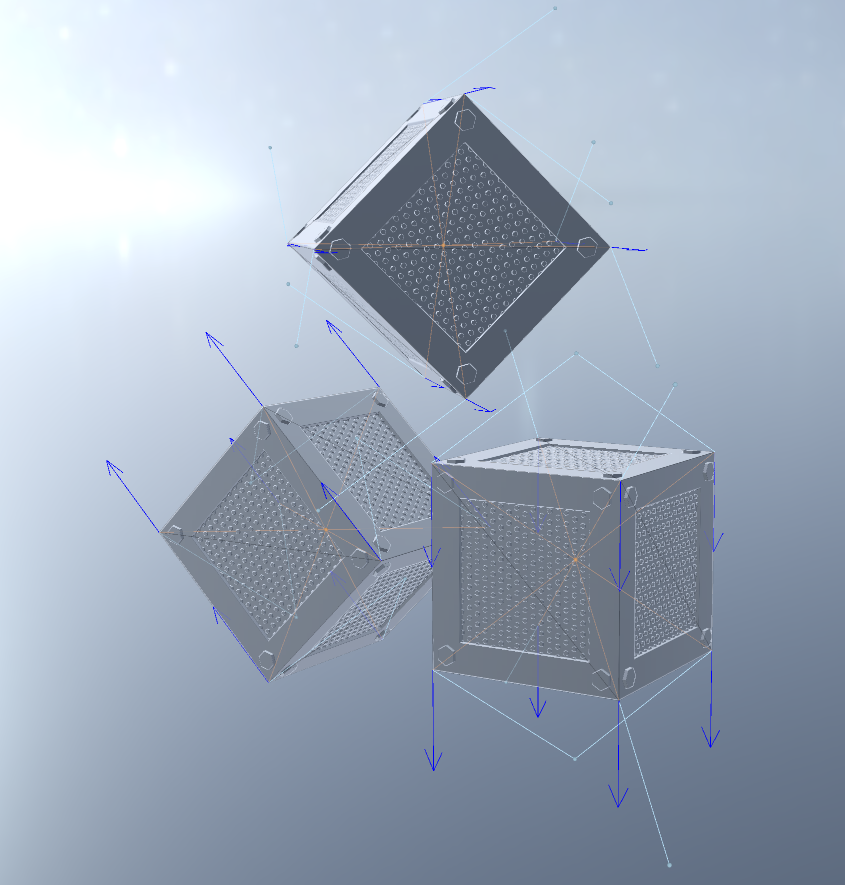
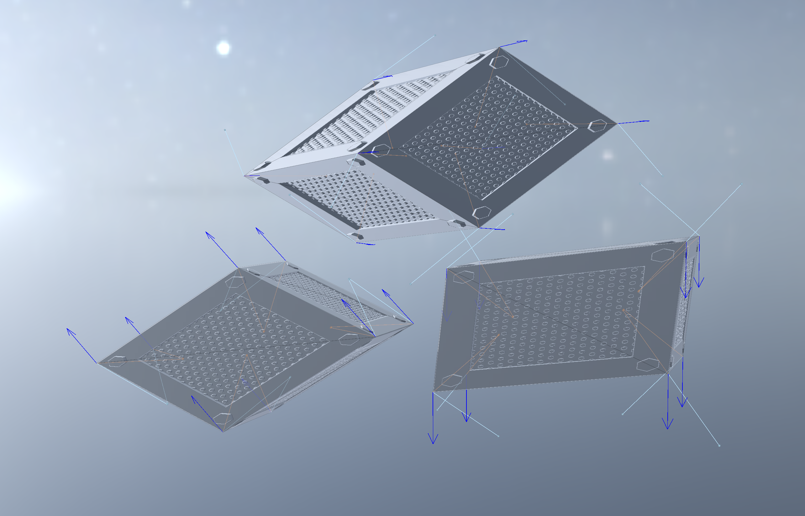
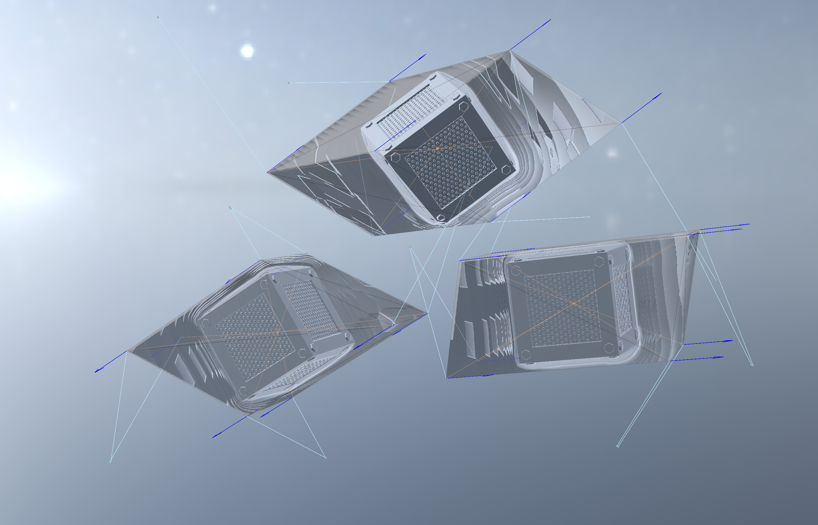
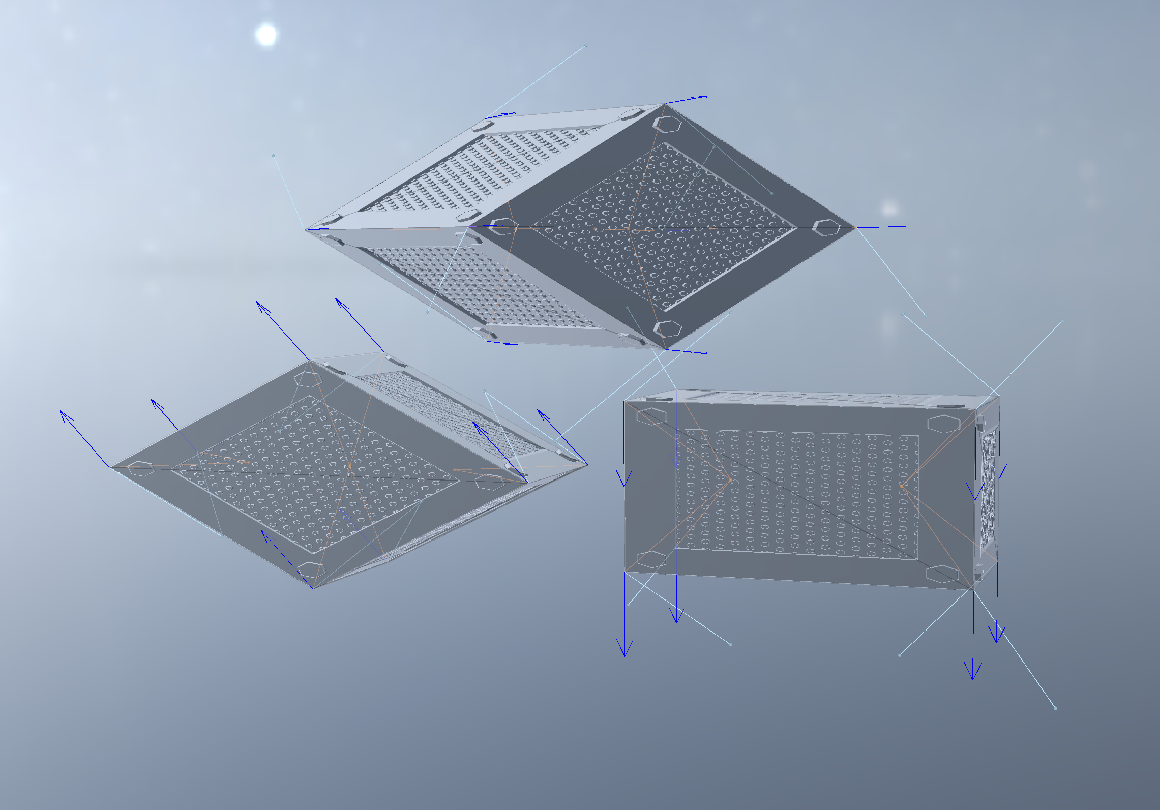
Finally, I have a Unity script which lets you visualize the raw baked vectors, and the “corrected” baked vectors, i.e. those rotated with the baked quaternion. Simply attach “Decode vertex vectors” to your gameobject. The light blue vectors are raw vectors, and the orange ones are the corrected ones. The orange ones should converge at the center of each submesh. (It’s okay if they overshoot/undershoot, you can correct for that in your SDF.)